Relay power cut
Cutting relay power drops the throttle injection and hands the throttle back to the stock pedal circuit. No software is involved.
A low-cost drive-by-wire research platform for sim-to-real autonomy
Arizona State University
MS Computer Science Thesis - Work in Progress
Self-driving research vehicles are expensive, and most of them are closed. This project turns a used Yamaha G22E electric golf cart into an autonomous research platform built from off-the-shelf parts. It adds a software-controlled drive-by-wire layer to the cart without changing how it drives for a person behind the wheel.
The cart is the physical end of a graduate research project on moving autonomy software from simulation onto real hardware. Everything below is the platform that work runs on.
A strict split keeps the safety-critical parts simple. Linux computers are fast on average but can stall unpredictably, so the Linux computer only plans. A bare-metal microcontroller handles every electrical connection to the cart and enforces limits. Relays sit underneath everything and fall back to stock wiring whenever power is lost.
The relay cut and the watchdog were both proven on the bench before going on the cart. On the cart, all three failsafes were triggered while the wheels were spinning under software command, and each one stopped them. That was also the first time the accelerator interlock had been tested at all.
Cutting relay power drops the throttle injection and hands the throttle back to the stock pedal circuit. No software is involved.
Pulling the USB cable mid-command sets off the microcontroller's hardware watchdog, which returns the throttle to rest.
A safety operator holds the accelerator switch closed. When they let go, the stock controller stops the cart, whatever the software is commanding.
The brake follows the same rules. It cannot press while the throttle is open, and it has to let go before the throttle can return. If the link to the computer drops, the brake holds where it is instead of letting go, a choice that gets revisited before any test on the ground.
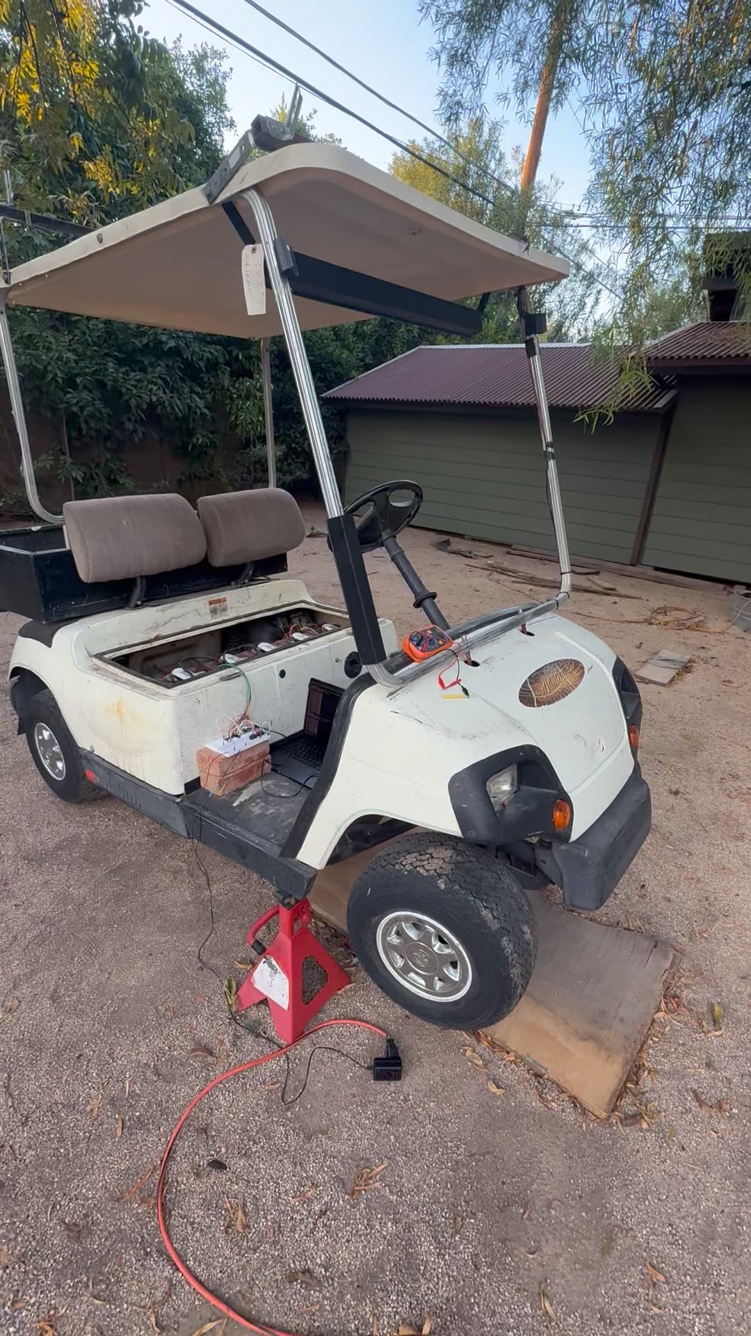
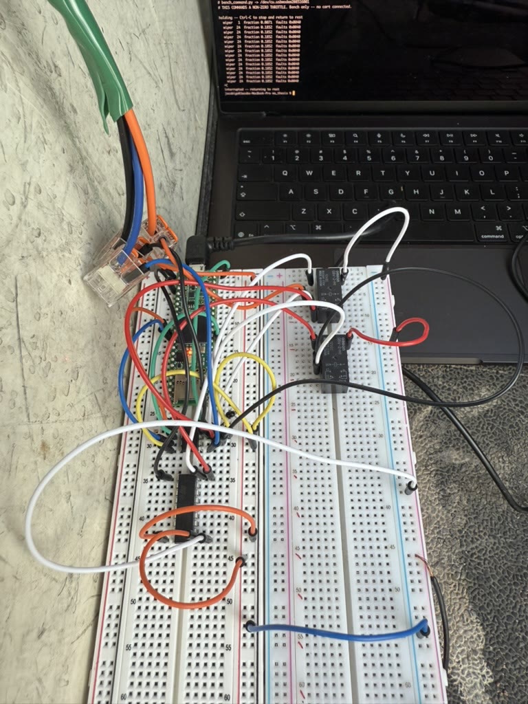
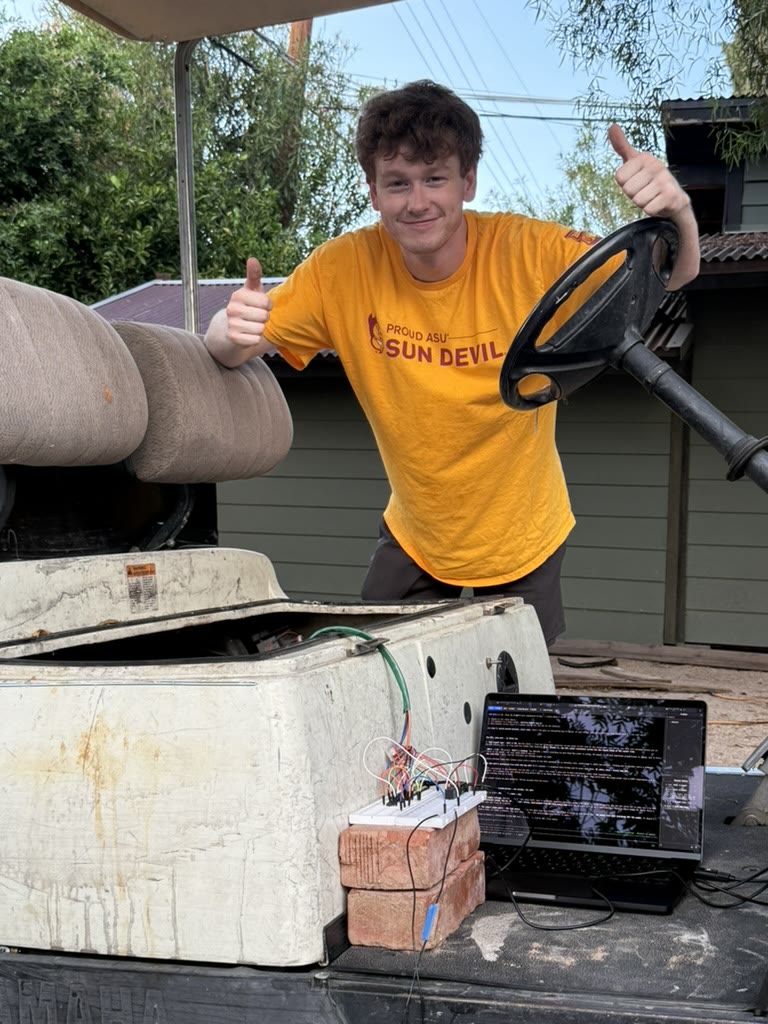
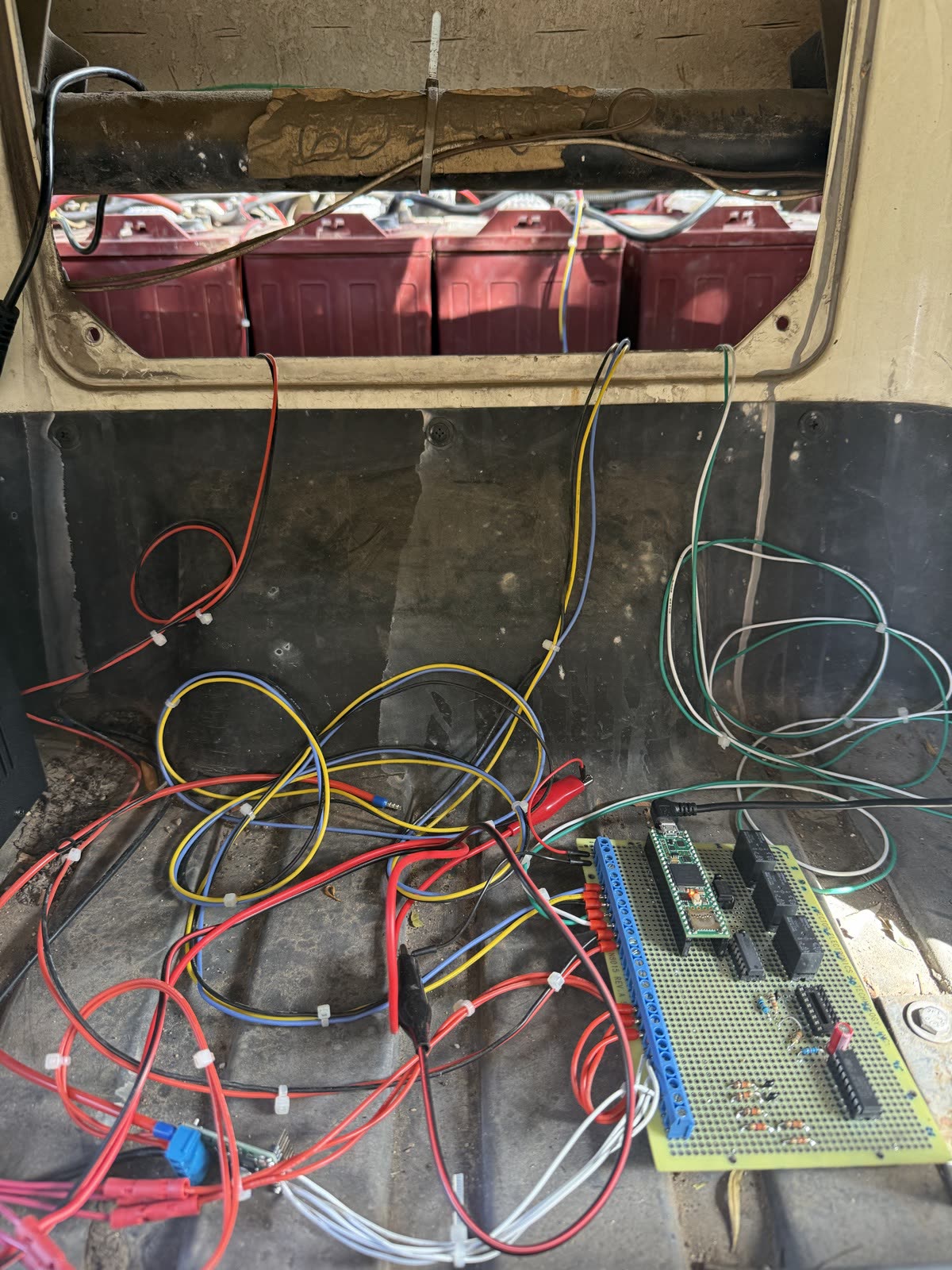
Hardware comes up one step at a time. Each stage adds one real component to the loop and has to pass before the next one starts.
A simulated serial link and a record-and-replay roundtrip, with no hardware attached.
The link works, using a custom binary protocol with CRC framing. Fault handling, including the hardware watchdog, was measured on the real board. The remaining fault cases can only be tested in later stages.
The microcontroller drives the digital potentiometer, checked against a meter. First end-to-end command from ROS to the output.
A resistor rig simulated the cart's controller on the bench, and every acceptance criterion was measured and passed.
With the cart on jackstands, the wheels turned under software command. All three failsafes stopped them mid-motion, and afterward the cart was put back to stock.
The microcontroller now reads the motor's speed sensor. Measuring how throttle maps to wheel speed gave a simple linear fit, which the controller uses as its first guess for any requested speed. A feedback loop corrects the rest. Tuned on jackstands, it reaches a new speed in about half a second without oscillating.
A walked survey of the driving area held a centimeter-level fix for over 90% of the run. With commanded speed, this closes the first milestone gate.
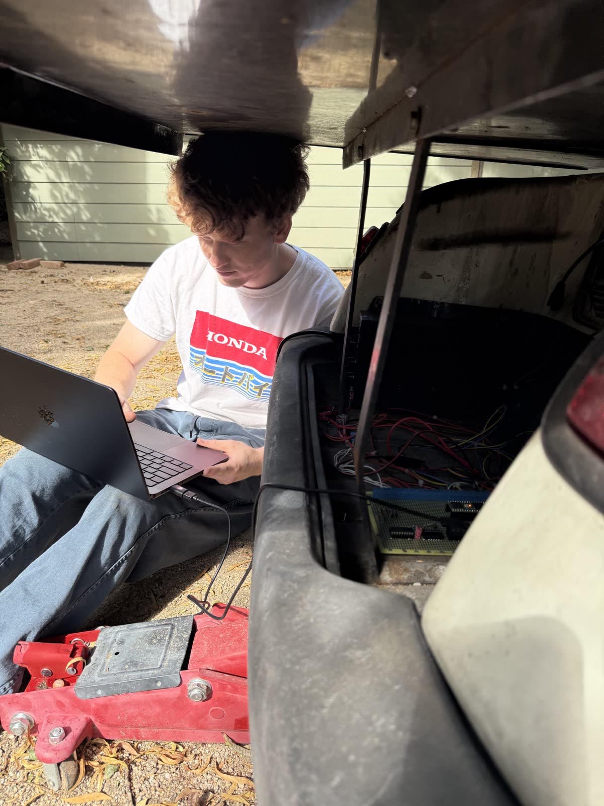
The electronics moved off the breadboard onto a soldered board, and it went on the cart. The wheels turned under commanded speed again, and the failsafes held: cutting relay power stopped them, and the link-loss cutoff fired within about a tenth of a second. It was still powered from a lab supply.
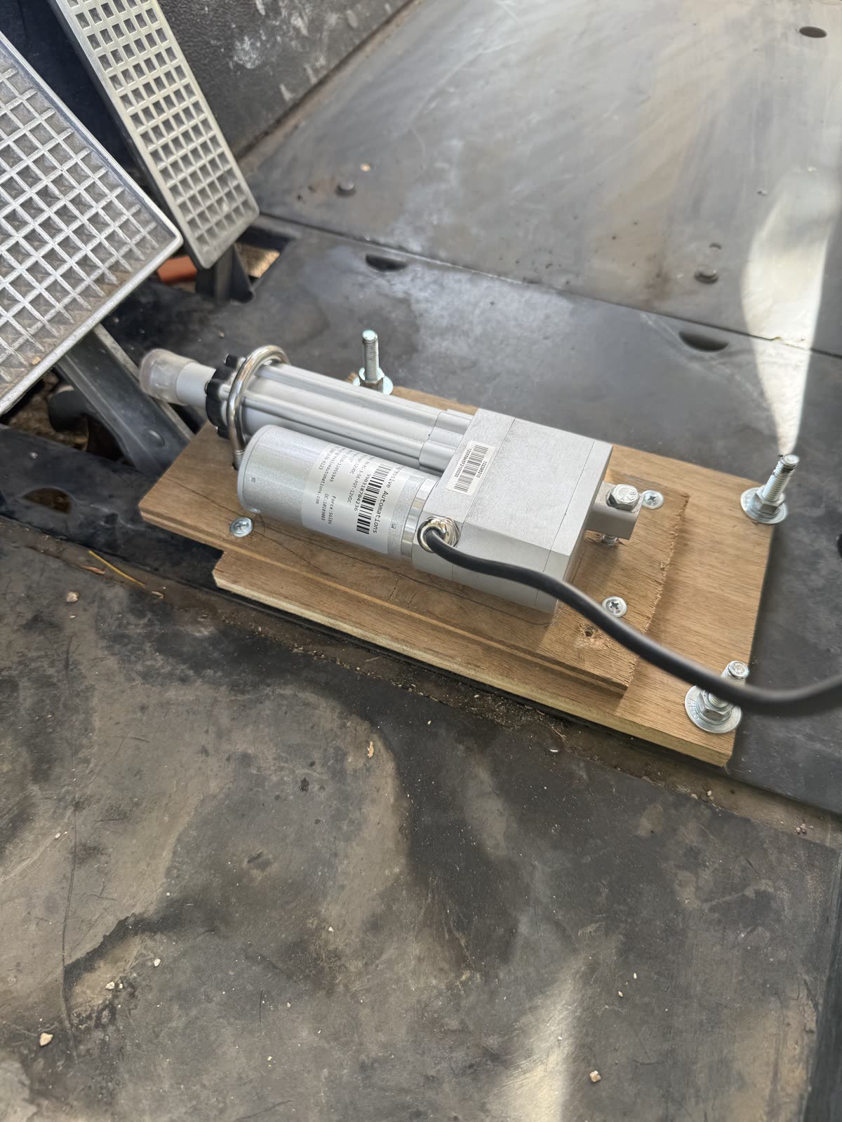
A linear actuator presses the brake pedal. It was brought up the same way as the throttle: on the bench, test-fit on the cart, then added to the cart's firmware. The speed-then-brake sequence now runs from one command, interlocked with the throttle.
Measuring how the cart stops, with a first holding test, and running everything from the cart's own battery pack.
An e-stop with no processor in its path. The cart does not drive itself until all of this passes.
The steering actuator, then the full autonomy stack on the cart.
This is a research platform tested on private property, with a safety operator present and speeds capped. It is not intended for public roads. All testing to date has been done with the drive wheels off the ground.